Thanks @nn62 for the explanation. (cc: @pietro and @mh973 )
Let me use some annotations to make sure I have a complete understanding.
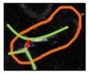
As stated earlier, all four of these calibrations are different variants of the same vessel structure shown below. The upper and lower vessels (in green) are clearly flowing (many moving blood cells) and the small “connector” (or separate vessel) (in red) does appear to be stalled.


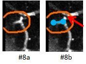
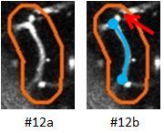
Let’s start with #8 and #12 since these represent a common error I am seeing in the annotations. Namely, branches of the primary vessels with stalls being annotated as stalled even though the targeted vessel is flowing.


You have restated that each outline is intended to highlight only a single vessel segment (from one joint to the next joint). Even though multiple segments may be included within a given outline, it is important to identify the targeted vessel segment and only classify this single segment as flowing or stalled. In the case of Calibration #8 and #12 shown above, these targeted segments are highlighted in blue in image #8b and #12b respectively, Therefore, the observed stall (red arrow) is not within the targeted vessel segment and should be ignored. Examples of this are observed in the real vessel population. I just want to be sure that these stalled branches from the targeted vessel should be ignored.
Calibrations #6 and #7 are a little more complicated.
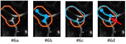
In these cases the outline itself inadvertently includes two different segments. (Over time you hope to improve the outlining accuracy, but for now, we will occasionally see errors like these.) Because the outline algorithm makes these occasional errors, we as players need to help interpret what was intended.
For Calibration #6 both the upper left vessel segment and the connector segment appear to be outlined as can be seen by the obvious downward turn in the outline in image #6a. I believe you are asking us to only focus on the larger vessel segment if more than one are included in the outline. The outline should have looked more like the blue outline in image #6c. In this case the smaller segment would be considered an extraneous branch (image #6d) and should be ignored.
.
I believe this is the same logic to be used for classifying Calibration #7 shown below.

The outline inadvertently included the short connector segment. The outline should have looked like the blue outline in image #7c. Again, we would be expected to ignore the stall (red arrow) and indicate this vessel as flowing.
So, in short, the “expert” explanation would be more like “Targeted vessel is flowing, extraneous stall(s) in branch vessels should be ignored.” This is true for all four calibrations identified above.
Please confirm my understanding is correct.
@gcalkins
 you don’t need to bother to answer because I’m sure you have plenty of truly important things to do it was just a thought that would make for a little less frustration for newbies, for me at least